E-mail
hydraulic directional valve
hydraulic directional flow valve

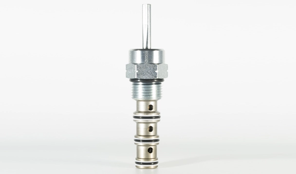
IMR10-47A Manual Directional Valve

This valve enables operators to manually adjust the direction of fluid flow, allowing precise control over the operation of hydraulic machinery and equipment. With its robust construction and user-friendly design, the IMR10-47A Manual Directional Valve provides reliable performance and ensures efficient directional control. Whether used in industrial machinery, mobile equipment, or other hydraulic applications, this valve offers a practical solution for operators to manage fluid flow and achieve desired functionality with ease.

Products

Specifications of IMR10-47A Manual Directional Valve

Operating Pressure240 bar (3500 psi)
FlowSee Performance Chart
Internal Leakage
164 ml/min. max (10 cu. in./minute) at 207 bar (3000 psi)
Temperature-40 to 100°C
FluidsMineral-based or synthetics with lubricating properties at viscosities of 7.4
to 420 cSt (50 to 2000 ssu)
InstallationNo restrictions
CavityIVC10-4; See page 302


Material

CartridgeWeight: 0.13kg. (0.29 lbs.); Steel with hardened work surfaces.
Zinc-plated exposed surfaces.
Seal: D type seal ring.
Standard Ported BodyWeight: 0.34 kg. (0.75 lbs.); Anodized high-strength 6061
T6 aluminum alloy, rated to 240 bar (3500 psi).
Ductile iron and steel bodies available; dimensions may differ.
Consult Inno.
Lever-Type Handle(Sold Separately): Weight: 0.18 kg. (0.38 lbs.);
Steel with hardened work surfaces. Zinc-plated exposed surfaces.
Plastic lever arm.


Features of IMR10-47A Manual Directional Valve

1. Three-position detent, friction lock (with detented neutral), or spring return
operators may be ordered separately.
2. May be fully pressurized at all ports.
3. Optional lock-down bracket.
4. Heavy-duty construction.
5. Industry common cavity.


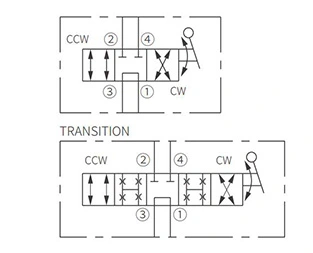
Operation Symbol of IMR10-47A Manual Directional Valve

Operation Symbol of IMR10-47A Manual Directional Valve

Three positions: centered, 45° counterclockwise, and 45° clockwise. In the center position, ports ① and ③ are open while ports ② and ④ are closed. In the 45°  counterclockwise from the center position, ports ① and ④ are open while ports ② and ③ are open. In the 45° clockwise from the center position, ports ① and ② are open while ports ③ and ④ are open. All ports are partially open in transition.

Performance/Dimension/Sectional Drawing of IMR10-47A Manual Directional Valve

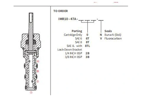
Sectional Drawing
Performance/Dimension/Sectional Drawing of IMR10-47A Manual Directional Valve
PERFORMANCE (cartridge only)
Performance/Dimension/Sectional Drawing of IMR10-47A Manual Directional Valve
DIMENSION (inch/mm)
Performance/Dimension/Sectional Drawing of IMR10-47A Manual Directional Valve
Latest News & Blogs From INNO
Quick Links
Contact
0086-553-8812880 salesinno@innohydra.com
No. 03, 03rd Kechuang Road, Xinwu Economic Development Zone, Wanzhi District, Wuhu City, Anhui Province, China
Follow Us
Contact
0086-553-8812880 salesinno@innohydra.com
No. 03, 03rd Kechuang Road, Xinwu Economic Development Zone, Wanzhi District, Wuhu City, Anhui Province, China
Follow Us